Capturing Model Rocket Telemetry Using a Raspberry Pi Zero (Part 1)
Q&A on Hacker News about this project
It seems like everyone's getting back into old hobbies in the time of COVID-19. For me, that's come as model rocketry, something I spent quite a bit of time doing growing up in the Appalachian Mountains of Pennsylvania. On a whim, I bought a model rocket a few weeks back, built it, and launched it while visiting home in PA. Armed with excitement from this rediscovered hobby – along with the admiration of two young nieces who were sure the rocket was going to the moon – I decided it was time to kick things up a notch and custom build a rocket and telemetry module.
Hardware Selection #
Basing this entire project around a Raspberry Pi Zero was an obvious choice to me because of its light weight and excellent ecosystem of easily-programmed sensors available. From there, it was a matter of selecting the types of sensors and other hardware I'd need to build into this project. I came up with the following:
Power #
- Lithium Ion Cylindrical Battery - 3.7v 2200mAh - A fairly light battery that outputs plenty of power. I also chose it because, being cylindrical, it seemed easy to secure it centered in the rocket body.
- PowerBoost 500 Basic - 5V USB Boost @ 500mA from 1.8V+ - This boosts the output of the battery to the 5V needed by the Pi.
Sensors #
- Adafruit BMP388 - Precision Barometric Pressure and Altimeter - The purpose of this, primarily, is to capture altitude, but it also records temperature and pressure. (Altitude is derived from pressure, in this case.)
- Triple-axis Accelerometer+Magnetometer (Compass) Board - LSM303 - This determines the attitude of the rocket.
- Zero Spy Camera for Raspberry Pi Zero - Pointed out the side of the rocket, this can grab some awesome images.
Telemetry Transmission/Reception #
- Adafruit RFM95W LoRa Radio Transceiver Breakout - 868 or 915 MHz - RadioFruit - This is a very cool module that transmits byte array packets at 868 or 915 MHz. (At first, I tried a cheaper 433 MHz module from another vendor and it did not work at all.) I bought two of these so I could use one to transmit and one to receive.
With all of these components chosen, I wired them up to a Raspberry Pi Zero. (First via breadboard for testing then soldered for final assembly.) For more on the wiring, see the appendix.
Wiring #
The air hardware is wired to the following Raspberry Pi pins:
- PowerBoost 500 Basic:
- 5v -> Pi 5V
- Ground -> Pi Ground
- BMP388 (SPI 0)
- VIN -> Pi 3V
- GND -> Pi GND
- SCK -> Pi SCLK
- SDI -> Pi MOSI
- SDO -> Pi MISO
- CS -> D5
- LSM303 (I2C)
- VIN -> Pi 3V
- GND -> Pi GND
- SCL -> Pi SCL
- SDA -> Pi SDA
- Camera
- Pi Camera ribbon connection
- RFM95W (SPI 1)
- VIN -> Pi 3V
- GND -> Pi GND
- SCK -> Pi SPI1 SCLK
- SDI -> Pi SPI1 MOSI
- SDO -> Pi SPI1 MISO
- CS -> Pi D24
- RST -> CE0
The ground hardware, much more simply, is wired to the following Raspberry Pi pins:
- RFM95W (SPI 1)
- VIN -> Pi 3V
- GND -> Pi GND
- SCK -> Pi SCLK
- SDI -> Pi MOSI
- SDO -> Pi MISO
- CS -> Pi CE1
- RST -> Pi D25
Software Development #
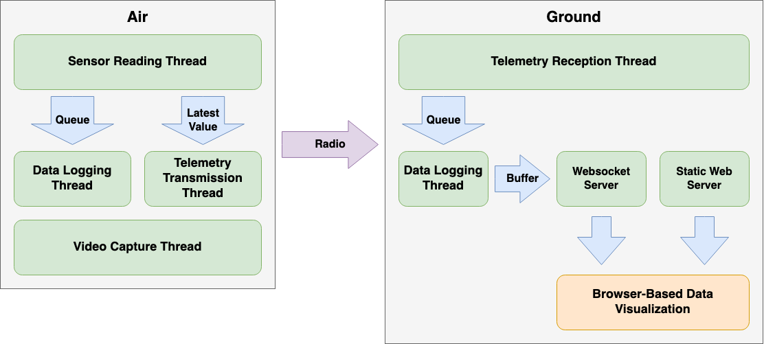
Before building the rocket and housings for the hardware, I needed to test the electronics and architect a software solution that would optimize for a high data sample rate. With that goal in mind, I devised the following:
To see the source, check out the GitHub Project. I've named the software White Vest after the iconic white vest that flight director Gene Kranz wore during Apollo 13.
Air #
In the sensor reading thread, I access two devices, the BMP388 and LSM303. Those values for pressure, temperature, acceleration, and magnetic orientation get added to a thread-safe queue and a thread-safe single value holder. This thread is able to capture about 4 sets of sensor readings per second. (Unfortunately the BMP388 reads out data quite slowly.)
A separate thread reads the thread-safe queue and logs that data to a CSV file on the device. Further, an additional thread reads that thread-safe single value and transmits that data via the RFM95W as floats packed into a byte array. (I only transmit the most-recently-read data rather than everything from the queue because I want the ground receiver to have near-realtime data.)
Finally a third thread records video from the camera. All data recording terminates 30 minutes after program start, but it will continue to transmit telemetry.
Ground #
On the ground, the RFM95W receives those transmitted byte arrays,unpacks them to floats, and puts the data into a thread-safe queue. Another thread reads from that thread-safe queue, logs that data to a CSV file, and appends the data to a thread-safe data buffer.
A third thread acts as a webserver to serve the dashboard web app, and a final thread listens for websocket connections to stream the contents of the data buffer as data becomes available.
Hardware Assembly #
With the electronics tested and operational, I designed a set of 3D printable components to mount the telemetry module in a rocket. Based on the Estes builders' kit I was using, I knew 4cm across was the widest body I could support. Therefore I designed a mounting system to support a tube of that width.
After a few iterations, I ultimately designed the following parts for printing:
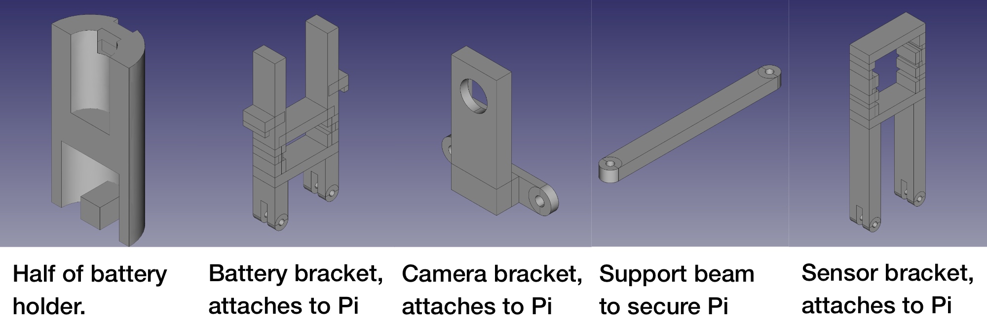
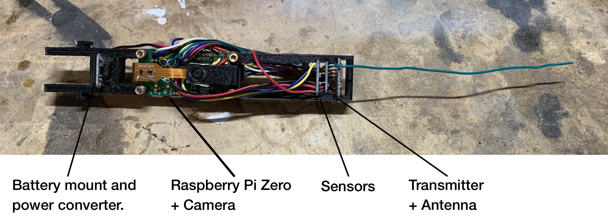
Those pieces, when assembled with the electronics, look like this:
Rocket Design #
The rocket has two main components: The booster section, which is the bottom half of the rocket, and contains the motor, fins, and recovery parachute. That section is joined via a coupler (one of the 3D-printed parts) to the upper-half of the rocket, which is the payload section containing the telemetry module.
After the main launch motor burns out, the engine fires an ejection charge up into the rocket. That force pushes the parachute up and blows out the coupler, forcing the two sections to separate and the parachute to deploy. (Both sections are attached to the parachute via shock cord.)
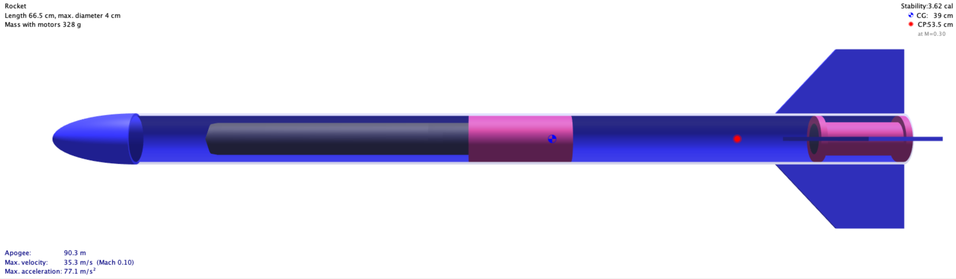
The graphic above is from my design in OpenRocket, which is an open source tool for designing and testing model rockets. To learn more about the principles of model rocket design, I suggest the classic book, Handbook of Model Rocketry, which is considered a go-to resource for the hobby.
Based on this design, using an Estes D12-5 motor, I could expect this rocket to top out at around 90 meters, or about 295 feet. There are more powerful motors available, but those require more sophisticated launch controllers and this was just first test.
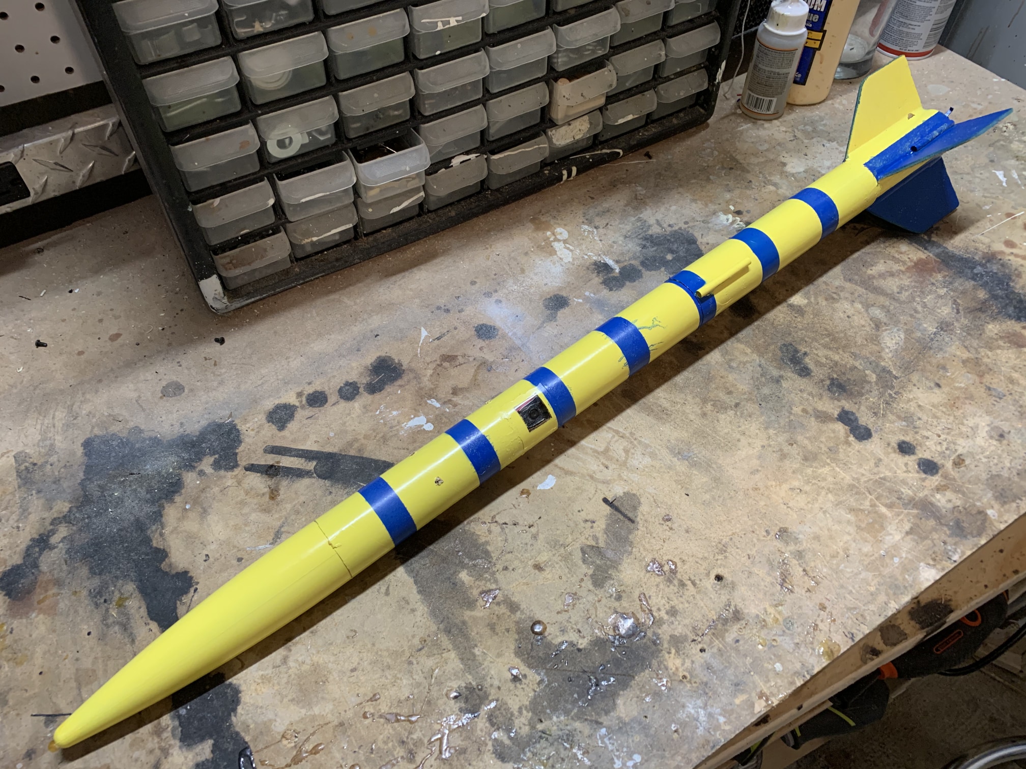
Once assembled, the rocket looked like this:
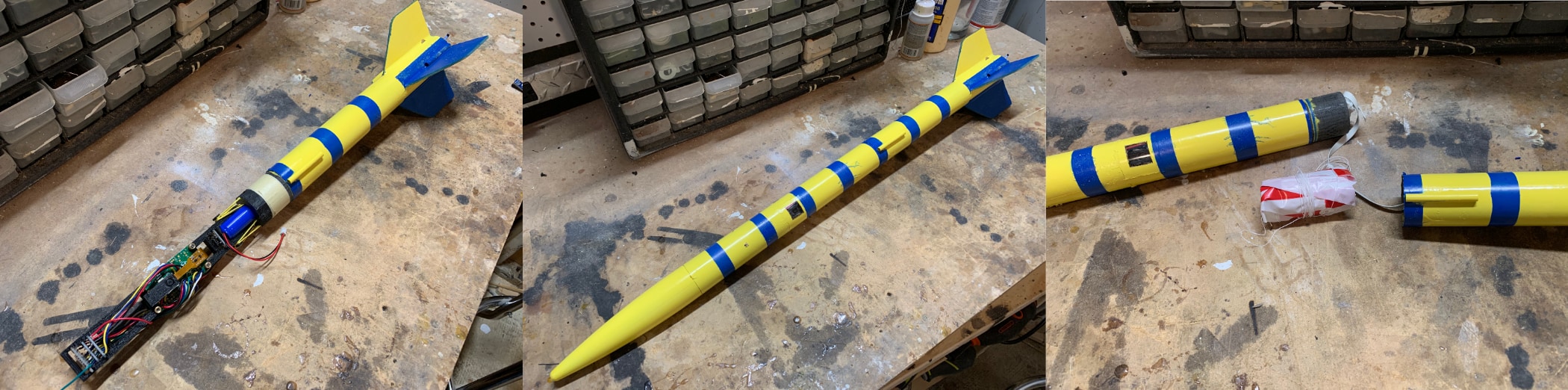
To see the results of launching this, check out Part 2