I Built a Bluetooth Low Energy, ESP32-Based Darkroom and Film Development Timer
Developing is just subjecting exposed film or paper to a series of chemical reactions. It involves "developing" which brings out the exposed image, "stopping" which halts the chemical reaction of developing to freeze the image, and "fixing" which removes light sensitivity from the medium so it can be viewed in normal light. All chemical reactions are sensitive to quantity, temperature, and time, and different films and developers have different developing time requirements. Develop for too long or too short a time and it changes the quality of the image.
There's a niche category of darkroom timer apps, but I had two key issues with them. First, some offer a "darkroom" mode that turns the interface all red, but that doesn't stop notifications or accidental swipes from interrupting and causing exposure mistakes. And second, darkrooms are wet areas because of the chemicals. That doesn't play nicely with phones.
So, I decided to build my own solution!
Design #
The darkroom timer apps have one key advantage: develop time selection. Because of all the combinations of film, developer, temperature, etc, there are a multitude of options to sort through when developing. I therefore chose to not design any sort of interface for the timer itself - rather I chose to implement the interface as an app and transmit the time selection to the timer using Bluetooth Low Energy.
The timer itself would just need a button to start the timer. After each timer completes, it would advance to the next timer (given that developing is a three-step process, a different timer is needed for each step).
Electronics #
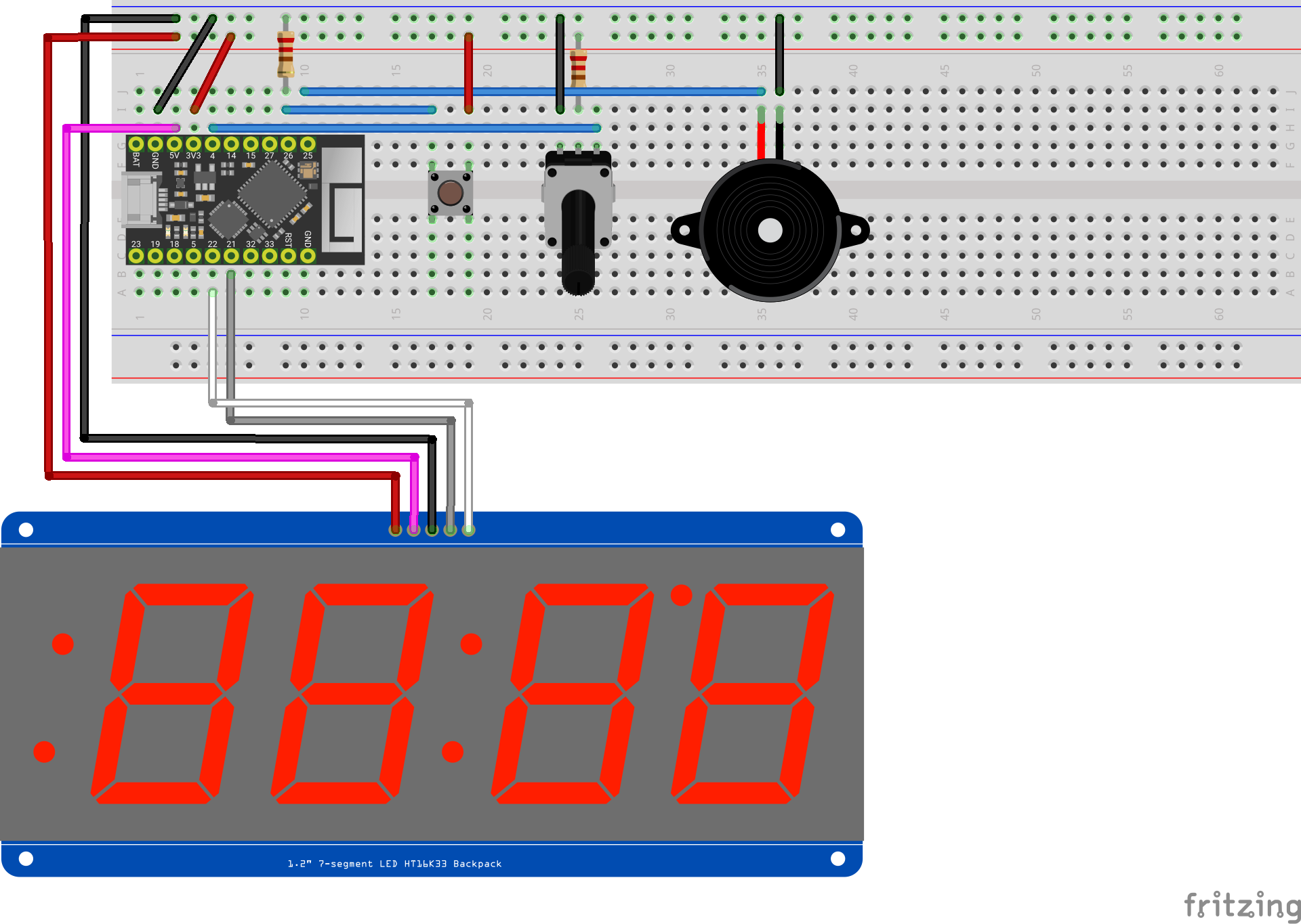
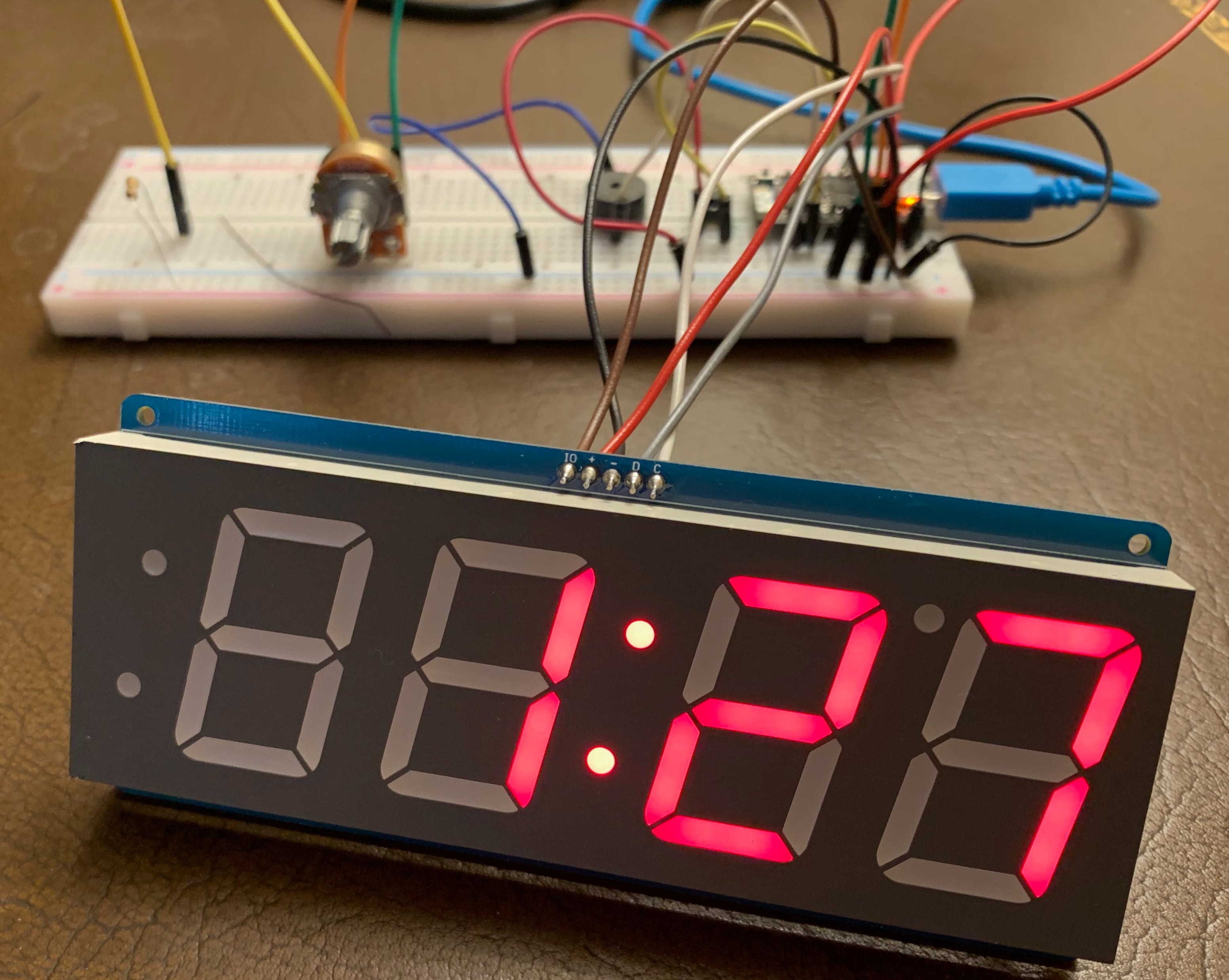
For the timer itself, not having an interface meant it could be very simple: it just needed a four-digit seven-segment display, a button to start/skip the current timer, and a way to adjust the brightness. For the display, Adafruit had a perfect red 1.2inch display that interfaces via I2C. To control the display and receive the times I chose the ESP32-based TinyPico because of its built in BLE module, I2C pins, and analog pins. A momentary pushbutton starts the timer, and a potentiometer connected to an analog pin sets the display's brightness. A buzzer also sounds when each timer completes.
Software #
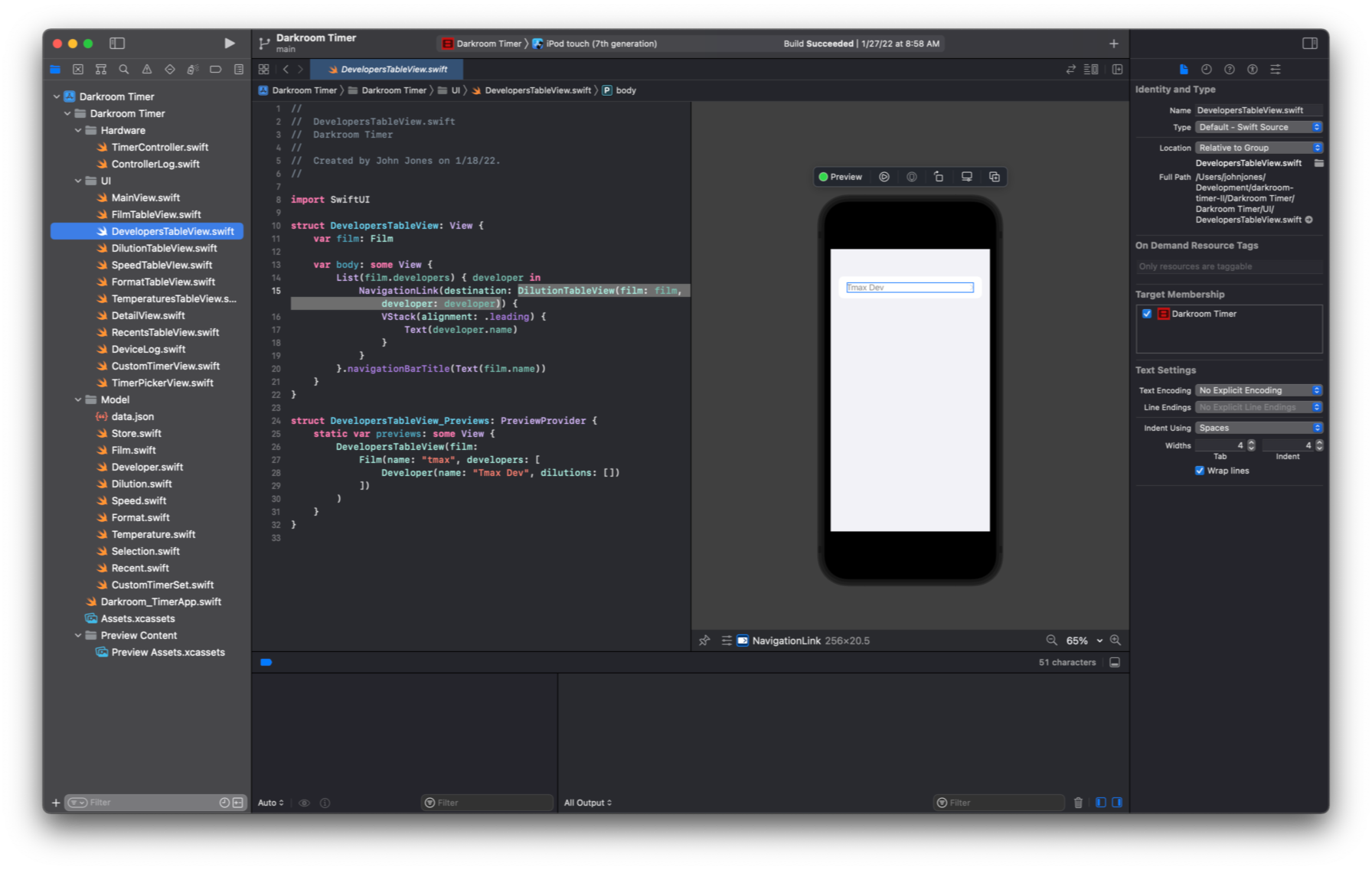
The data from the app comes from a film community website that has an extensive
database of films and developers. This was my first project using the new(ish)
SwiftUI interface design feature in iOS development, and it made wiring up the
data models to a series of drilldown tables an absolute breeze. It doesn't seem
to have all the customization options of the long used UITableView but for
simple needs it is far better. In the app, I also added the ability to define a
custom sequence of timers as well.

To send the selected set of times to the timer in a BLE message, I designed a
custom data format that encodes an array of integers into a byte array. The
first byte of the message contains the "start character," ASCII code 0x02,
the second byte is an unsigned integer that's the number of timers in the
message, and then the rest of the message are an amount of two byte pairs
specified in that length bit. Each pair is an unsigned 16 bit integer of
seconds. The last part of the message is the ASCII code 0x03 to signal the
end of the message.
Send: #
func send(times: [UInt16]) {
    var message = Data()

    message.append(MessageStart)

    message.append(UInt8(times.count))

    times.forEach { time in
        let parts : [UInt8] = [
            UInt8(time & 0x00FF),
            UInt8(time >> 8)
        ]
        parts.forEach { part in
            message.append(part)
        }
    }

    message.append(MessageEnd)

    if let clockDevice = self.clockDevice, let clockCharacteristic = self.clockCharacteristic {
        clockDevice.writeValue(message, for: clockCharacteristic, type: CBCharacteristicWriteType.withResponse)
    }
}
Receive: #
bool readBLE() {
  std::string value = pCharacteristic->getValue();
  if (value.compare(lastBLEValue) == 0) {
    return false;
  }
  lastBLEValue = value;
  const char* bytes = value.c_str();
  int l = value.length();
  if (bytes[0] != MESSAGE_START) {
    return false;
  }
  int length = uint8_t(bytes[1]);
  if (length >= MAX_LENGTH || length == 0 || bytes[2 + (length * 2)] != MESSAGE_END) {
    return false;
  }
  for (int i = 0; i < length; i++) {
     timerSet[i] = uint16_t(bytes[(i * 2) + 2]) | (uint16_t(bytes[(i * 2) + 3]) << 8);
     Serial.printf("Seconds: %d\n", timerSet[i]);
  }
  currentTimersN = length;
  return true;
}Enclosure #
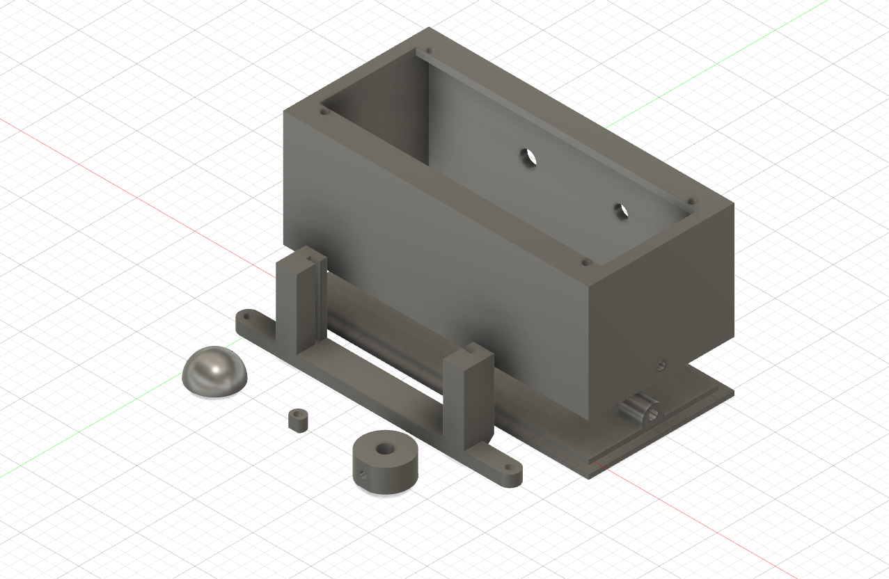
I modeled the enclosure in Fusion360. The parts are:
- The enclosure
- A mount for the perfboard
- Spacers to flush the display against the front of the case
- A knob for the potentiometer
- A dome-shaped cover for the button
Download the STLs on Thingiverse